
OFDR Analysis of Silicon Wavelength (De)Multiplexer Using Cascaded MZIs and Apodized Waveguide Gratings
- Latitude Design Systems
- Oct 22, 2024
- 3 min read
Introduction
Wavelength (de)multiplexers are crucial components in wavelength-division multiplexing (WDM) optical communication systems, enabling multiple wavelengths to be transmitted over a single fiber. Silicon photonics technology offers a promising platform for realizing compact and low-cost wavelength (de)multiplexers due to its high-index contrast and CMOS compatibility. This tutorial discusses the design, fabrication, and characterization of a silicon wavelength (de)multiplexer based on cascaded Mach-Zehnder interferometers (MZIs) and apodized waveguide gratings using optical frequency-domain reflectometry (OFDR).
Design and Fabrication
The wavelength (de)multiplexer circuit comprises cascaded MZIs combined with grating-based Michelson interferometers (GMIs) for additional optical filtering. The cascaded MZIs are designed to interleave four optical channels with a 5 nm spacing in the C-band, utilizing a fabrication-tolerant MZI design to ensure high tolerance to manufacturing linewidth variations.
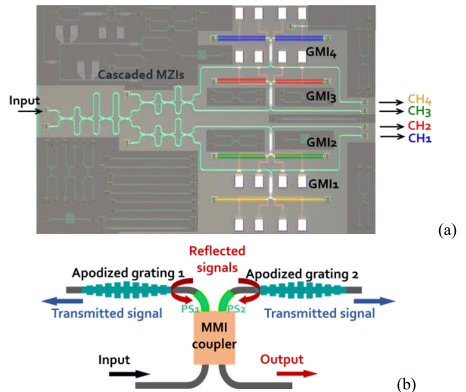
Each GMI consists of two apodized waveguide gratings with identical pitches connected to the output ports of a multimode interference coupler, as shown in Figure 1(b). Four GMIs with different grating pitches are employed to form optical passbands at 1540, 1545, 1550, and 1555 nm, respectively. Gaussian apodization is applied to the sidewall gratings to realize a sidelobe-free spectral response, creating a perfect optical bandpass filter at the GMI outputs.
The wavelength (de)multiplexer was fabricated using CMOS-compatible processes with 193-nm deep-UV lithography provided by a foundry. Figure 1(a) shows a microscopic view of the as-fabricated GMI-assisted cascaded MZIs.
Characterization
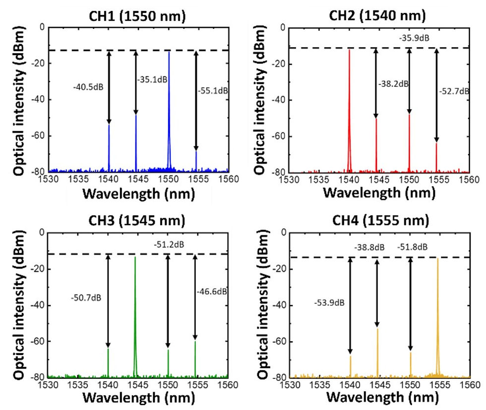
The optical spectra at the outputs of the GMI-assisted cascaded MZIs were measured by simultaneously injecting optical signals with wavelengths of 1540, 1545, 1550, and 1555 nm. As shown in Figure 2, with the help of the GMIs, the optical crosstalk is significantly reduced to less than -35 dB for all channels.
To better understand the behavior of the GMI-assisted cascaded MZIs, optical frequency-domain reflectometry (OFDR) was employed to extract the propagation loss of waveguide sections and the reflection amplitudes of the discontinuities along the circuit.
OFDR Analysis
An optical reflectometer (OBR 4600 from Luna Innovations Inc.) was connected to the input of the GMI-assisted cascaded MZIs through a single-mode fiber. The time-domain and wavelength-domain reflections were measured, as shown in Figures 3(a) and 3(b), respectively.
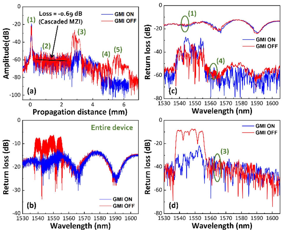
The time-domain trace in Figure 3(a) resolves discontinuities at (1) the input grating coupler, (3) the GMIs, and (4) the output grating couplers. The smooth light propagation region between (1) and (3) corresponds to the cascaded MZIs, and its insertion loss can be extracted from the slope of the trace in this region, which is approximately 0.69 dB.
The wavelength-domain data in Figure 3(b) shows up to -15 dB optical return loss when the GMI is ON over the 1530~1610 nm wavelength range. Four reflection peaks are added to the trace when the GMI is switched OFF.
To investigate the impacts of each discontinuity on the overall response, a small length span was used to cover the regions (1), (3), and (4) separately for further fast Fourier transform (FFT) operations, yielding the wavelength-domain reflection spectra shown in Figures 3(c) and 3(d).
The results reveal that the interface reflection of the GMIs can be reduced to below -25 dB when it is ON, but the overall reflection is dominated by the input grating coupler, which demands around -20 dB over a broad wavelength range.
Conclusions
This work employed OFDR to analyze a complex optical circuit combining cascaded MZIs and GMIs for wavelength (de)multiplexing. The obtained time-domain data was used to extract the insertion loss (-0.69 dB) of the cascaded MZIs, while the wavelength-domain data was applied to investigate the optical reflection at discontinuities (< -25 dB at GMIs).
Combined with the transmission spectra exhibiting low optical crosstalk and proper wavelength registration, the authors concluded that the GMI-assisted cascaded MZIs are a promising solution for wavelength (de)multiplexing. Additionally, OFDR proved to be a useful tool for assisting in the development of complex photonic integrated circuits.
In summary, this tutorial article discussed the design, fabrication, and characterization of a silicon wavelength (de)multiplexer based on cascaded MZIs and apodized waveguide gratings. The use of OFDR enabled detailed analysis of the circuit's performance, including the extraction of propagation losses, reflection amplitudes, and the identification of dominant sources of reflection. The results demonstrated the potential of this approach for realizing low-loss and low-crosstalk wavelength (de)multiplexers in silicon photonics.
Reference
C.-C. Chen, W.-X. Chen, C.-C. Hung, C.-T. Wang, C.-C. Chou, Y.-J. Hung, "OFDR Characterization of Silicon Wavelength (De)Multiplexer Based on Cascaded MZIs and Apodized Waveguide Gratings," Department of Photonics, National Sun Yat-sen University, Kaohsiung, Taiwan, 2024, pp. 1-6, doi: 979-8-3503-9404-7/24/$31.00 ©2024 IEEE.
Komentāri