High Q-Factor Integrated Resonators in the Long-Wave Infrared Range
- Latitude Design Systems

- Nov 8, 2024
- 3 min read
Introduction
The mid-infrared (mid-IR) wavelength range, spanning from 5-15 μm, is highly significant for various applications, particularly in environmental and toxic vapor sensing. This is because many relevant molecules exhibit strong absorption lines within this spectral region. The development of photonic integrated circuits operating in the mid-IR range is crucial for realizing robust, portable, and widespread sensing detectors. Among the various photonic devices required for integrated circuits, integrated resonators are of great interest as they can serve as building blocks for many device developments, including wavelength filters, optoelectronic modulators, and frequency comb generators.
Despite recent progress in the silicon photonics platform for the mid-IR range, there have been only a few reports of integrated resonators operating beyond 6 μm wavelength. This tutorial article presents the development of wideband resonators operating in the 7.5-9 μm wavelength range, also known as the long-wave infrared (LWIR) spectral range. Remarkably, Q-factors up to 10^5 have been measured, paving the way for the use of these devices in the development of microresonator-based comb generators operating in the LWIR range.
Device Design
One of the main challenges in characterizing high Q-factor resonators operating in a wide spectral range of the mid-IR is the required resolution, which is not easily achievable in existing setups. To overcome this issue, a thermal heater was introduced close to the resonator. Narrow wavelength features can thus be measured using a fixed narrow linewidth laser and tuning the phase in the resonator by adjusting the electrical power dissipated in the metallic heater.
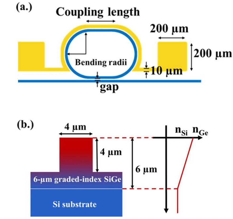
Figure 1 shows the schematic view of the device and the waveguide cross-section. The device consists of a 6 μm-thick graded SiGe waveguide, with a linear variation of the Ge concentration from pure Si close to the Si substrate to pure Ge on top of the waveguide. The waveguide width and etching depth are 4 μm. The gap between the bus waveguide and the resonator is 1 μm, the coupling length is 10 μm, and the resonator radius is 350 μm. These dimensions were determined through numerical simulations.

Experimental Results
The first measurement aimed to evaluate the spectral range of the resonator. This was done using a tunable external cavity quantum cascade laser (QCL). The results, shown in Figure 2(a), reveal resonance dips corresponding to the cavity's free spectral range (FSR) across the entire 7.8-8.8 μm wavelength range. However, the measured spectrum is irregular in amplitude, which could be mistakenly attributed to poor resonator performance. This irregularity is mainly due to the laser linewidth, which is around 1 cm^-1, corresponding to 6 nm at 8 μm wavelength.

To characterize the resonator performance with better resolution, a second measurement was performed using a tunable laser operating in continuous wave (CW) mode. The laser linewidth is much narrower (<100 MHz, corresponding to 20 pm at 8 μm wavelength), allowing the probing of cavity resonances with Q-factors up to 4 × 10^5. However, the wavelength sweep is limited by the minimum tuning step size (0.6 nm at 8 μm wavelength). Therefore, thermal heaters were used to tune the phase in the resonator and describe the resonance peak.
The results are shown in Figures 2(b) and 2(c). Figure 2(b) reports the full width at half maximum (FWHM) of the resonator at different wavelengths. It can be observed that the FWHM increases with wavelength, which can be attributed to an increase in propagation losses in the bent waveguides at longer wavelengths. The smallest FWHM is obtained at 7.45 μm wavelength.
Figure 2(c) shows the measured transmission spectrum at 7.45 μm wavelength, where both Fabry-Perot fringes from the device facets and the resonance from the racetrack resonator can be seen. The numerical fit used to extract the FWHM is shown in red. A FWHM of 0.074 nm was obtained at 7.45 μm wavelength, corresponding to a loaded Q-factor of 1.01 × 10^5. Considering this loaded Q-factor and the transmission at resonance, the intrinsic Q-factor was deduced to be 1.13 × 10^5, corresponding to total propagation losses of 1.2 dB/cm inside the resonator.
Finally, these results were confirmed by measuring the transmission of the device using a distributed feedback quantum cascade laser (DFB-QCL), which provides the advantage of fine wavelength scanning but with a limited spectral range (8.496–8.548 μm). Good agreement was obtained between the results from the two different experimental setups within this wavelength range.
Conclusion
This work demonstrates high Q-factor integrated resonators operating in the 7.5-9 μm wavelength range, exploiting Ge-rich graded SiGe photonics circuits. The main result is the achievement of integrated resonators with a Q-factor higher than 10^5 at 7.4 μm wavelength. This paves the way for future applications of integrated resonators in sensing or communication applications in the long-wave infrared spectral range.
Reference
[2] N. Koompai et al., "High Q-factor (>105) integrated resonators in the 7.5-9 µm wavelength range," Centre de Nanosciences et de Nanotechnologies, CNRS, Univ. Paris-Sud, Université Paris-Saclay, Palaiseau, France, 2024, pp. 1-6, doi: 979-8-3503-9404-7/24/$31.00 ©2024 IEEE.


Comments