
Introduction
Optical interactions based on optomechanical effects have emerged as a promising research area, finding applications in diverse fields such as telecommunications, quantum technologies, high-resolution spectroscopy, and sensing. One particularly interesting optomechanical phenomenon is the Brillouin dynamic grating (BDG), which offers unique advantages over traditional stimulated Brillouin scattering (SBS).
The BDG is a form of Brillouin enhanced four-wave mixing, where two pump waves interact to create an acoustic wave that then reflects a third, orthogonally polarized probe wave. This process results in a tunable optical filter with properties that can be dynamically adjusted through purely optical means. Compared to regular SBS, BDGs offer several key advantages:
1. Larger frequency separation: The frequency difference between the pumps and probe in a BDG can be tens of nanometers, much larger than the typical 10 GHz separation in SBS. This makes it easier to separate the pump and probe signals, reducing noise.
2. Polarization discrimination: Since the probe is orthogonally polarized to the pumps, a polarization beam splitter can be used to efficiently combine and split the signals.
3. Dynamic tunability: The bandwidth and time delay of the BDG can be adjusted by controlling the length of the acoustic grating, which is determined by the overlap region of the pump pulses. This dynamic tunability makes the BDG a uniquely agile filter.
BDGs have been extensively studied in optical fibers, but their integration into chip-scale platforms has been limited. Until now, the only observation of a BDG in an integrated waveguide has been in a chalcogenide-based material, which, while a great host for Brillouin scattering, has limited integrability and potential for large-scale circuit integration.
In this tutorial, we will explore the first observation of a BDG in a standard, low-loss silicon nitride (Si3N4) waveguide platform. Silicon nitride is a mature integrated photonics material with a large library of microwave photonics components, making it an ideal candidate for harnessing the unique capabilities of BDGs.
Operating Principle of Brillouin Dynamic Gratings
The creation and probing of Brillouin dynamic gratings is a four-wave mixing process that is supported by stimulated Brillouin scattering (SBS). In SBS, a probe wave interacts with a counter-propagating, higher-power pump wave that is detuned from the probe by a frequency on the order of 10 GHz. If this frequency difference matches the Brillouin frequency of the waveguide, ΩB, the interference between the pump and probe creates an acoustic wave through electrostriction. This acoustic wave then creates a moving Bragg-like grating via the photoelastic effect, which reflects the pump light, resulting in amplification of the probe.
To extend this SBS process into the generation of a BDG, a second pump wave is introduced, as shown in Figure 1. Both pumps are in the transverse electric (TE) polarization and generate an acoustic wave as described above. A new probe wave, in the transverse magnetic (TM) polarization and co-propagating with the higher-frequency pump 1, is then used to characterize the acoustic grating.
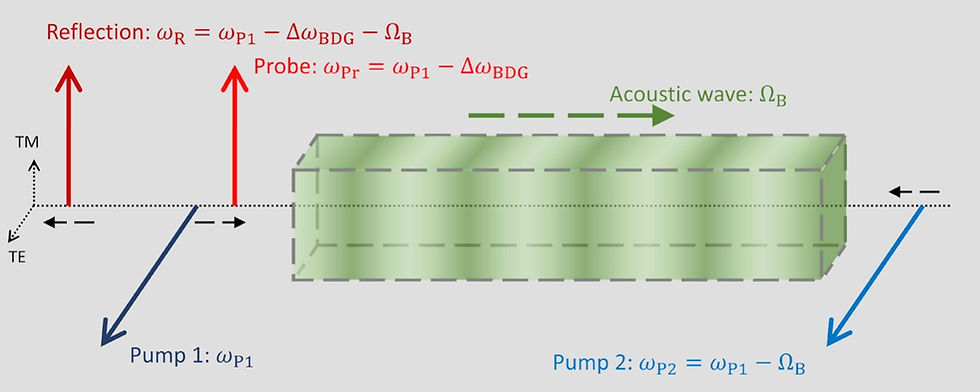
When the wavelength of the probe light matches the grating period, it will be reflected by the acoustic grating, undergoing a Doppler shift equal to the Brillouin frequency, ΩB. This allows the frequency separation between the pumps and probe to be much larger than the typical 10 GHz seen in SBS, on the order of tens of nanometers depending on the birefringence of the waveguide.
The key advantage of the BDG is its dynamic tunability. Assuming the grating is weak, the bandwidth, Δω, of the BDG is determined by:
Δω = πc / (neffTML)
where c is the speed of light, neff,TM is the effective refractive index of the TM mode, and L is the grating length. By pulsing the pump waves, the length of the grating can be controlled, allowing the bandwidth to be tuned. Additionally, the time delay of the reflected probe can be adjusted by changing the location where the pump pulses overlap and create the grating. These two dynamic parameters make the BDG a uniquely agile optical filter.
Waveguide Design and Properties
In this work, the researchers used silicon nitride waveguides with a symmetric double stripe (SDS) geometry, as shown in Figure 2(a). This waveguide consists of two 150 nm thick silicon nitride (Si3N4) layers separated by a 500 nm layer of silicon oxide (SiO2). The waveguides were designed to support single-mode operation of the TE00 mode, with low-loss chip-to-fiber coupling and a low bending radius of 100 μm.
The researchers selected a 1.4 μm wide waveguide for their experiments, as it had the highest Brillouin gain coefficient (0.25 m-1 W-1) and lowest propagation loss (0.206 dB/cm) among the available waveguides with a simulated probe wavelength above 1500 nm. The waveguide was 50 cm long, folded into a quasi-rectangular spiral.
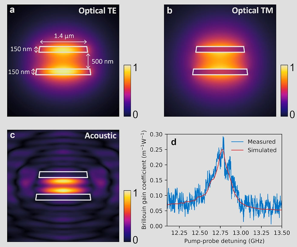
At the pump wavelength of 1556 nm, the TE mode has an effective index of 1.543, while the probe wavelength, calculated to be 1502 nm, has an effective TM index of 1.490 (Figures 2(a) and 2(b)). The acoustic mode at the peak Brillouin shift of 12.76 GHz is shown in Figure 2(c). Simulations indicate that the TM mode has significantly higher coupling and bend losses compared to the TE mode, which will limit the propagation of the probe light and the strength of the BDG signal.
Experimental Setup
The experimental setup used to observe the BDG in the silicon nitride waveguide is shown in Figure 3. The two pump waves are derived from the same laser source, an APIC Ultra Low Noise Laser, to ensure mutual frequency stability. Pump 2 is created by modulating the laser output using an intensity modulator and selecting the lower sideband with an interleaver. Pump 1 is amplified to a higher power.
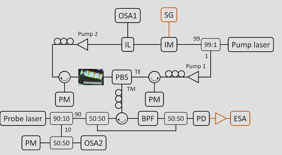
The probe light is generated using a hybrid integrated laser, consisting of an indium phosphide gain section and a silicon nitride feedback circuit. This laser is tuned to the BDG frequency, outputting 8.59 dBm of power.
The probe light is combined with pump 1 using a polarization beam splitter (PBS) and coupled into the silicon nitride waveguide. Pump 2 is sent into the waveguide from the opposite direction, also in the TE polarization. The reflected BDG signal is filtered from the pumps using a PBS and further filtered with a tunable bandpass filter. The signal is then combined with a portion of the probe light for heterodyne detection on a photodiode. The RF signal is analyzed using an electrical spectrum analyzer (ESA).
Results and Discussion
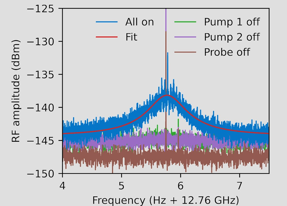
After scanning the probe laser around 1502 nm, the researchers observed a clear response when the probe was at 1501.92 nm, as shown in Figure 4. To verify that this signal was indeed due to the BDG interaction, they repeated the measurement with one of the three light sources turned off, and no signal was present in those cases.
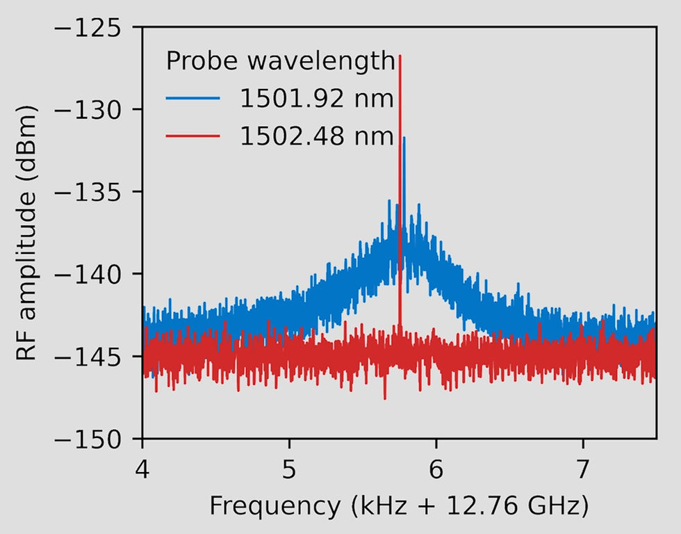
Further confirmation was obtained by tuning the probe wavelength by more than 61 GHz, the estimated maximum BDG bandwidth, whereupon the signal disappeared, as shown in Figure 5.
The measured BDG signal had a peak power of -138.1 dBm at the ESA, which, after accounting for the gain block amplification and various losses, corresponds to a reflected optical power of -125.2 dBm on the chip. Comparing this to the input probe power gives a reflectivity of 5.4 × 10⁻¹³, which is much lower than previous on-chip BDG observations.
The researchers attribute this lower reflectivity to the high TM mode losses in the waveguide, which limit the effective grating length and, consequently, the BDG signal strength. However, they have designed a new sample to address this issue and further enhance the BDG response.
The new design features waveguides with a larger 300 μm bend radius, which will significantly reduce the TM mode losses. Additionally, the waveguides have been optimized for TM mode coupling, reducing the losses by around 4.5 dB compared to the TE mode. These improvements, combined with a longer 1 m waveguide length, are expected to increase the BDG reflectivity by over two orders of magnitude, unlocking the path to large-scale integration and various applications of this unique optical filter.
Conclusion
In this tutorial, we have explored the first observation of a Brillouin dynamic grating in a standard, low-loss silicon nitride waveguide platform. The BDG offers unique advantages over traditional stimulated Brillouin scattering, including a larger frequency separation between the pumps and probe, polarization discrimination, and dynamic tunability of the filter properties.
While the initial BDG signal observed in the silicon nitride waveguide was relatively weak due to high TM mode losses, the researchers have designed a new sample with optimized waveguide parameters to significantly enhance the BDG response. By reducing the TM mode losses and increasing the waveguide length, they expect to achieve over a 100-fold increase in the BDG reflectivity, paving the way for the integration of this versatile optical filter into large-scale microwave photonics circuits.
The integration of Brillouin dynamic gratings into the silicon nitride platform represents an important milestone in the development of advanced optomechanical devices on chip. As the researchers continue to optimize the design and explore various applications of the BDG, we can expect to see exciting advancements in areas such as microwave photonics, quantum technologies, and high-precision sensing.
Reference
[2] R. Botter, J. van den Hoogen, A. Mishra, K. Ye, A. van Rees, M. Hoekman, K. Boller, and D. Marpaung, "Observation of a Brillouin dynamic grating in silicon nitride waveguides," APL Photon., vol. 9, no. 046105, Apr. 2024. [Online]. Available: https://doi.org/10.1063/5.0178804
Kommentare