top of page

Distributed Quantum Computing with Silicon T Centres

Introduction

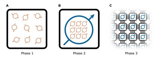
Quantum computers hold great promise for solving certain problems much faster than classical computers. However, building large-scale quantum computers capable of running commercially relevant algorithms remains a significant challenge. One approach to scaling quantum computers is through distributed architectures, where multiple quantum processor modules are networked together.

In this article, we will explore the use of silicon T centres as a platform for distributed quantum computing. T centres are optically active defects in silicon that combine excellent spin properties with the ability to emit photons in the telecom wavelength range. By integrating T centres into silicon photonic devices and connecting them via optical fibers, it becomes possible to create a scalable, modular quantum computing architecture.

Phases of quantum computing
FIG. 1. Phases of quantum computing: A. Phase 1 (NISQ) involves single modules with noisy physical qubits (orange) that cannot implement QEC. B. Phase 2 still involves single modules but with sufficient, low-noise physical qubits to encode logical qubits (blue). C. Phase 3 features multi-module quantum computers capable of implementing large-scale quantum algorithms fault-tolerantly.
T Centre Basics

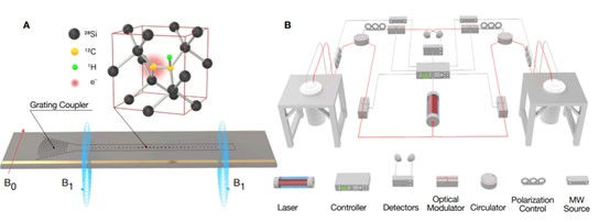
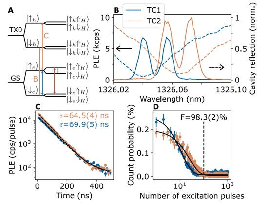
T centres consist of a hydrogen atom bonded to a carbon atom in the silicon lattice (Fig. 2A). The electronic structure of the T centre includes a ground state (GS) with electron and nuclear spin states, and an optically excited state (TX0) with a bound exciton. Under an external magnetic field, the optical transition splits into two spin-selective transitions (labeled B and C) that can be used for spin initialization, readout, and remote entanglement generation (Fig. 3A).

To create T centres suitable for quantum computing, isotopically purified silicon is used to eliminate unwanted nuclear spins. The T centres are then integrated into photonic cavities on silicon-on-insulator (SOI) chips, which enhances their optical emission properties via the Purcell effect (Fig. 3B-C).

Schematic of the demonstration
FIG. 2. Schematic of the demonstration: A. T centre in a silicon lattice within an optical cavity on a photonic chip, excited by light via a grating coupler, with spin transitions driven by microwave and RF drives from a metal antenna. Magnetic field B0 is applied in-plane and B1 is generated from on-chip antennas out-of-plane. B. Two T centre qubit modules separated by ~40 meters of fibre, with optical fibre in red and electrical/microwave lines in grey. Optical modulators include acousto-optic, electro-optic, and semiconductor optical modulators on the excitation path, and an acousto-optic modulator on the collection path.
Individual T centre optical performance
FIG. 3. Individual T centre optical performance: A. Fine structure of a T centre under a magnetic field showing electron (|↑e⟩), excited state hole (|↑h⟩), and hydrogen (|⇑H⟩) spins. Splittings include GS to TX0, electron/hole Zeeman splitting, and electron-nuclear hyperfine. B. PLE spectra of TC1 and TC2 at a magnetic field of 122.3 mT, with cavity resonances in dashed lines. C. Purcell-enhanced lifetimes of the C and B transitions of TC1 and TC2. D. Initialization of T centres from optical pumping, with an initialization fidelity of 98.3(2)%.
Spin Control and Readout

Full control over the T centre spin states is achieved using microwave (MW) and radio-frequency (RF) pulses delivered via on-chip antennas. Electron spin transitions are driven using MW pulses (Fig. 4A-B), while nuclear spin transitions are driven using RF pulses (Fig. 4C-D). By applying appropriate pulse sequences, universal quantum gates such as controlled-NOT (CNOT) can be implemented.

Single-shot readout of the nuclear spin state is performed by mapping it onto the electron spin, which is then read out optically (Fig. 4E). This allows for high-fidelity state preparation and measurement (SPAM) of the nuclear spin qubit.

The T centres used in this work demonstrate exceptional spin coherence times (Fig. 5), with electron spin T2 times of up to 270 μs and nuclear spin T2 times of up to 220 ms. These long coherence times are crucial for implementing high-fidelity quantum operations.

Individual T centre spin performance
FIG. 4. Individual T centre spin performance: A. ODMR showing PLE signal vs. MW frequency with two nuclear-spin-selective MW transition frequencies. B. Coherent Rabi oscillations driving the MW⇓ nuclear-spin-selective transition, where a π rotation constitutes a CHNOTe gate (inset: ground state energy level diagram). C. ODMR spectrum showing the resonant frequency of a nuclear transition. D. Coherent Rabi oscillations driving an electron-spin-selective nuclear transition, where a π rotation constitutes a CeNOTH (inset: ground state energy level diagram). E. Nuclear spin preparation and measurement: photon counts for nuclear spins in up or down states (inset: pulse sequence for initialization and readout, state preparation and measurement fidelity vs. photon number threshold).
Spin coherence times
FIG. 5. Spin coherence times: A. Electron Rabi oscillations without nuclear selectivity (inset: driven transition). B, C. Ramsey interference fringes showing T∗2 decay for electron and nuclear spins (inset: pulse sequence). D, E. Hahn-echo T2 decay curves for electron and nuclear spins (inset: pulse sequence). Improvements in materials and fabrication could significantly enhance the coherence times of device-integrated T centres, approaching those observed in bulk 28Si (0.28 s for nuclear spins and 2.1 ms for electron spins).
Remote Entanglement

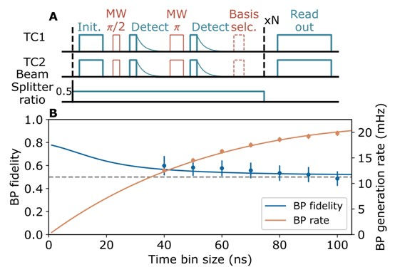
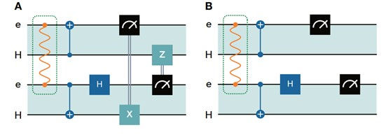
To enable distributed quantum computing, remote entanglement must be established between T centres on different chips. This is achieved using a protocol known as Barrett-Kok (BK) (Fig. 7A), which relies on the interference of photons emitted by the T centres.

The key requirement for successful entanglement generation is the indistinguishability of the emitted photons. This is quantified by the Hong-Ou-Mandel (HOM) visibility (Fig. 6), which measures the degree of quantum interference between photons from different T centres. By optimizing the spectral and temporal properties of the T centres, high-visibility HOM interference can be achieved.

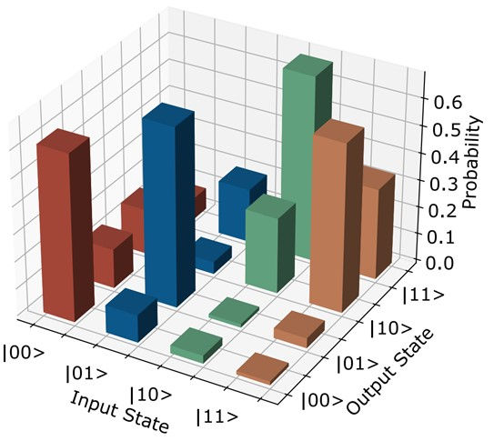
Using the BK protocol, remote entanglement of T centre electron spins was demonstrated with fidelities up to 60% (Fig. 7B). The generated entanglement was then used to perform a teleported CNOT gate between the nuclear spin qubits of the remote T centres (Fig. 8-9), showcasing the potential for distributed quantum logic.

Hong-Ou-Mandel two-photon interference
FIG. 7. Demonstration of the Barrett-Kok protocol: A. Pulse sequence for BP entanglement, with initialization by optical pumping followed by the entangling sequence. The final microwave pulse determines the basis for readout. B. BP generation rate and fidelity for various time bin sizes.
Teleported CNOT circuit diagrams
FIG. 8. Teleported CNOT circuit diagrams: A. A tCNOT between hydrogen nuclei (H) in T centres in different modules, highlighting the space between the electron (e) and nuclei in the same T centre. First, establish a distributed Bell pair on the electrons, then implement local measurements and operations to complete the tCNOT. B. Post-selected teleported CNOT circuit, achieved by omitting feed-forward operations and post-selecting on measurement outcome 00.
Truth table for the preliminary T centre teleported CNOT sequence
FIG. 9. Truth table for the preliminary T centre teleported CNOT sequence: Truth table for the initial tCNOT experiment using post-selected CNOT.
Outlook and Conclusion

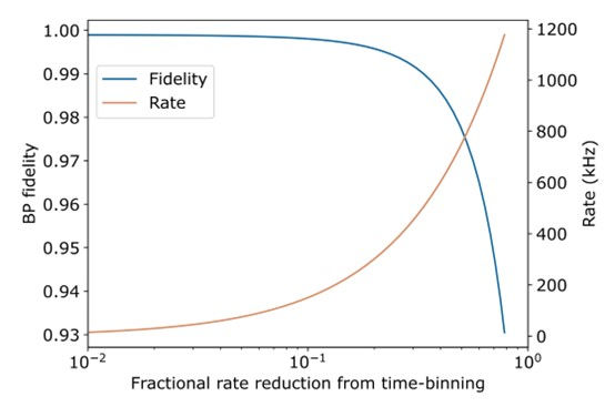
Based on the experimental results and projected improvements in T centre devices, it is expected that remote entanglement fidelities of up to 99.9% and distribution rates of 200 kHz can be achieved (Fig. 10). This would enable fault-tolerant distributed quantum computing across multiple T centre processor modules.

Silicon T centres offer a promising platform for realizing distributed quantum computers. By leveraging the mature silicon photonics industry and the excellent properties of T centres, it may be possible to build modular, scalable quantum computing systems capable of tackling commercially relevant problems. The results presented in this tutorial represent important first steps towards this goal, paving the way for future advancements in distributed quantum computing technology.

Fidelity and rate of remote Bell pair distribution using projected T centre performance
FIG. 10. Fidelity and rate of remote Bell pair distribution using projected T centre performance: A time-window correlation filter enhances entanglement fidelity and captures a fraction of total coincidences. Additional infidelity sources, such as double excitation and off-resonant excitation, are also considered.
Reference

[1] Photonic Inc., "Distributed Quantum Computing in Silicon," June 11, 2024.

Comments


bottom of page